
Page 310 - Complete Wireless Design
P. 310
Filter Design
Filter Design 309
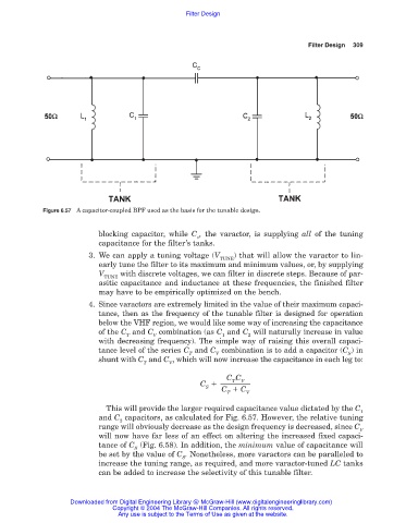
Figure 6.57 A capacitor-coupled BPF used as the basis for the tunable design.
blocking capacitor, while C , the varactor, is supplying all of the tuning
v
capacitance for the filter’s tanks.
3. We can apply a tuning voltage (V ) that will allow the varactor to lin-
TUNE
early tune the filter to its maximum and minimum values, or, by supplying
V with discrete voltages, we can filter in discrete steps. Because of par-
TUNE
asitic capacitance and inductance at these frequencies, the finished filter
may have to be empirically optimized on the bench.
4. Since varactors are extremely limited in the value of their maximum capaci-
tance, then as the frequency of the tunable filter is designed for operation
below the VHF region, we would like some way of increasing the capacitance
of the C and C combination (as C and C will naturally increase in value
T V 1 2
with decreasing frequency). The simple way of raising this overall capaci-
tance level of the series C and C combination is to add a capacitor (C ) in
T V S
shunt with C and C , which will now increase the capacitance in each leg to:
T V
C C
V
T
C
S
C C
T V
This will provide the larger required capacitance value dictated by the C
1
and C capacitors, as calculated for Fig. 6.57. However, the relative tuning
2
range will obviously decrease as the design frequency is decreased, since C
V
will now have far less of an effect on altering the increased fixed capaci-
tance of C (Fig. 6.58). In addition, the minimum value of capacitance will
S
be set by the value of C . Nonetheless, more varactors can be paralleled to
S
increase the tuning range, as required, and more varactor-tuned LC tanks
can be added to increase the selectivity of this tunable filter.
Downloaded from Digital Engineering Library @ McGraw-Hill (www.digitalengineeringlibrary.com)
Copyright © 2004 The McGraw-Hill Companies. All rights reserved.
Any use is subject to the Terms of Use as given at the website.