
Page 309 - Complete Wireless Design
P. 309
Filter Design
308 Chapter Six
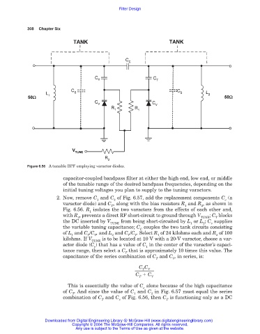
Figure 6.56 A tunable BPF employing varactor diodes.
capacitor-coupled bandpass filter at either the high end, low end, or middle
of the tunable range of the desired bandpass frequencies, depending on the
initial tuning voltages you plan to supply to the tuning varactors.
2. Now, remove C and C of Fig. 6.57, add the replacement components C (a
1 2 v
varactor diode) and C , along with the bias resistors R and R , as shown in
T 1 2
Fig. 6.56. R isolates the two varactors from the effects of each other and,
1
with R , prevents a direct RF short-circuit to ground through V ; C blocks
2 TUNE T
the DC inserted by V from being short-circuited by L or L ; C supplies
TUNE 1 2 v
the variable tuning capacitance; C couples the two tank circuits consisting
C
of L and C /C , and L and C /C . Select R of 24 kilohms each and R of 100
1 T V 2 T V 1 2
kilohms. If V is to be located at 10 V with a 20-V varactor, choose a var-
TUNE
actor diode (C ) that has a value of C in the center of the varactor’s capaci-
v 1
tance range, then select a C that is approximately 10 times this value. The
T
capacitance of the series combination of C and C , in series, is:
T V
C C
T
V
C C
T V
This is essentially the value of C alone because of the high capacitance
v
of C . And since the value of C and C in Fig. 6.57 must equal the series
T 1 2
combination of C and C of Fig. 6.56, then C is functioning only as a DC
T v T
Downloaded from Digital Engineering Library @ McGraw-Hill (www.digitalengineeringlibrary.com)
Copyright © 2004 The McGraw-Hill Companies. All rights reserved.
Any use is subject to the Terms of Use as given at the website.