
Page 304 - Complete Wireless Design
P. 304
Filter Design
Filter Design 303
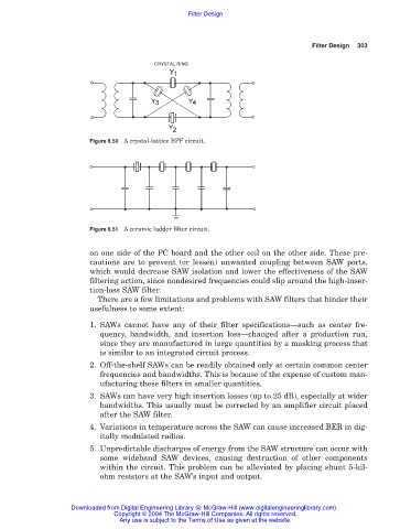
Figure 6.50 A crystal-lattice BPF circuit.
Figure 6.51 A ceramic ladder filter circuit.
on one side of the PC board and the other coil on the other side. These pre-
cautions are to prevent (or lessen) unwanted coupling between SAW ports,
which would decrease SAW isolation and lower the effectiveness of the SAW
filtering action, since nondesired frequencies could slip around the high-inser-
tion-loss SAW filter.
There are a few limitations and problems with SAW filters that hinder their
usefulness to some extent:
1. SAWs cannot have any of their filter specifications—such as center fre-
quency, bandwidth, and insertion loss—changed after a production run,
since they are manufactured in large quantities by a masking process that
is similar to an integrated circuit process.
2. Off-the-shelf SAWs can be readily obtained only at certain common center
frequencies and bandwidths. This is because of the expense of custom man-
ufacturing these filters in smaller quantities.
3. SAWs can have very high insertion losses (up to 25 dB), especially at wider
bandwidths. This usually must be corrected by an amplifier circuit placed
after the SAW filter.
4. Variations in temperature across the SAW can cause increased BER in dig-
itally modulated radios.
5. Unpredictable discharges of energy from the SAW structure can occur with
some wideband SAW devices, causing destruction of other components
within the circuit. This problem can be alleviated by placing shunt 5-kil-
ohm resistors at the SAW’s input and output.
Downloaded from Digital Engineering Library @ McGraw-Hill (www.digitalengineeringlibrary.com)
Copyright © 2004 The McGraw-Hill Companies. All rights reserved.
Any use is subject to the Terms of Use as given at the website.