Page 307 - Complete Wireless Design
P. 307

Filter Design


            306  Chapter Six


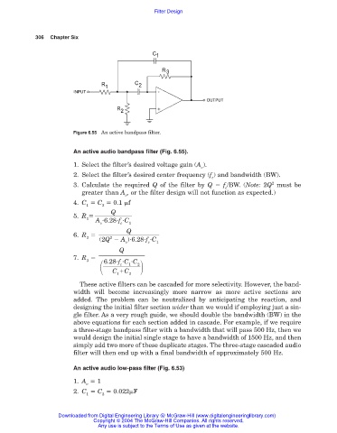
                        Figure 6.55 An active bandpass filter.


                        An active audio bandpass filter (Fig. 6.55).
                        1. Select the filter’s desired voltage gain (A ).
                                                                 v
                        2. Select the filter’s desired center frequency (f ) and bandwidth (BW).
                                                                    c
                                                                                       2
                        3. Calculate the required  Q of the filter by  Q   f /BW. (Note: 2Q must be
                                                                        c
                           greater than A , or the filter design will not function as expected.)
                                         v
                        4. C   C   0.1 
f
                            1    2
                                    Q
                        5. R
                            1
                               A  6.28 f  C
                                 v     c  1
                                         Q
                        6. R
                            2       2
                                (2Q   A ) 6.28 f  C
                                         v      c  1
                                       Q
                        7. R
                            3     6.28 f  C  C

                                            2
                                       c
                                          1
                                     C  C
                                      1   2
                          These active filters can be cascaded for more selectivity. However, the band-
                        width will become increasingly more narrow as more active sections are
                        added. The problem can be neutralized by anticipating the reaction, and
                        designing the initial filter section wider than we would if employing just a sin-
                        gle filter. As a very rough guide, we should double the bandwidth (BW) in the
                        above equations for each section added in cascade. For example, if we require
                        a three-stage bandpass filter with a bandwidth that will pass 500 Hz, then we
                        would design the initial single stage to have a bandwidth of 1500 Hz, and then
                        simply add two more of these duplicate stages. The three-stage cascaded audio
                        filter will then end up with a final bandwidth of approximately 500 Hz.
                        An active audio low-pass filter (Fig. 6.53)

                        1. A   1
                            v
                        2. C   C   0.022
F
                            1    2

                   Downloaded from Digital Engineering Library @ McGraw-Hill (www.digitalengineeringlibrary.com)
                               Copyright © 2004 The McGraw-Hill Companies. All rights reserved.
                                Any use is subject to the Terms of Use as given at the website.
   302   303   304   305   306   307   308   309   310   311   312