
Page 306 - Complete Wireless Design
P. 306
Filter Design
Filter Design 305
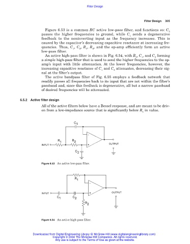
Figure 6.53 is a common RC active low-pass filter, and functions so: C
2
passes the higher frequencies to ground, while C sends a degenerative
1
feedback to the noninverting input as the frequency increases. This is
caused by the capacitor’s decreasing capacitive reactance at increasing fre-
quencies. Thus, C , C , R , R , and the op-amp efficiently form an active
1 2 1 2
low-pass filter.
An active high-pass filter is shown in Fig. 6.54, with R , C , and C forming
2 1 2
a simple high-pass filter that is used to send the higher frequencies to the op-
amp’s input with little attenuation. At the lower frequencies, however, the
increasing capacitive reactance of C and C attenuates, decreasing their sig-
1 2
nal at the filter’s output.
The active bandpass filter of Fig. 6.55 employs a feedback network that
readily passes all frequencies back to its input that are not within the filter’s
passband and, since this feedback is degenerative, all but a narrow passband
of desired frequencies will be attenuated.
6.5.2 Active filter design
All of the active filters below have a Bessel response, and are meant to be driv-
en from a low-impedance source that is significantly below R in value.
1
Figure 6.53 An active low-pass filter.
Figure 6.54 An active high-pass filter.
Downloaded from Digital Engineering Library @ McGraw-Hill (www.digitalengineeringlibrary.com)
Copyright © 2004 The McGraw-Hill Companies. All rights reserved.
Any use is subject to the Terms of Use as given at the website.