
Page 302 - Complete Wireless Design
P. 302
Filter Design
Filter Design 301
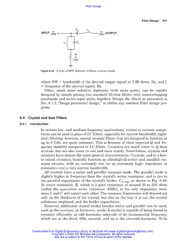
Figure 6.48 A type of BPF diplexer without a series input.
where BW bandwidth of the desired output signal at 3 dB down, Hz, and f
r
frequency of the desired signal, Hz.
Other, much more selective diplexers (with more poles), can be rapidly
designed by simply joining two standard 50-ohm filters, with nonoverlapping
passbands and series input poles, together. Design the filters as presented in
Sec. 6.1.3, “Image parameter design,” or utilize any common filter design pro-
gram.
6.4 Crystal and Saw Filters
6.4.1 Introduction
In certain low- and medium-frequency applications, crystal or ceramic compo-
nents can be used in place of LC filters, especially for narrow bandwidth, tight-
skirt filtering (however, special ceramic filters that are designed to function at
up to 6 GHz are quite common). This is because of their superior Q and fre-
quency stability compared to LC filters. Ceramics are much lower in Q than
crystals, but are also lower in cost and more sturdy. Nonetheless, crystals and
ceramics have almost the same general characteristics. Crystals, and to a less-
er extent ceramics, basically function as ultrahigh-Q series (and parallel) res-
onant circuits, with an extremely low (or an extremely high) impedance at
resonance over a very narrow bandwidth.
All crystals have a series and parallel resonant mode. The parallel mode is
slightly higher in frequency than the crystal’s series resonance, and is due to
the parallel capacitance of the crystal’s holder, C , as shown in Fig. 6.49.
PLATE
At series resonance, R, which is a pure resistance of around 25 to 250 ohms
[called the equivalent series resistance (ESR)], is the only impedance seen,
since L and C will cancel each other. The resonant frequencies will depend not
only on the thickness of the crystal, but also on the way it is cut, the crystal
substance employed, and the holder capacitance.
However, additional crystal modes besides series and parallel can be used,
such as the overtone, or harmonic, mode: A crystal is capable of being forced to
resonate efficiently at odd harmonic intervals of its fundamental frequency,
which are at the third, fifth, seventh, and up to the eleventh harmonic. To be
Downloaded from Digital Engineering Library @ McGraw-Hill (www.digitalengineeringlibrary.com)
Copyright © 2004 The McGraw-Hill Companies. All rights reserved.
Any use is subject to the Terms of Use as given at the website.