
Page 298 - Complete Wireless Design
P. 298
Filter Design
Filter Design 297
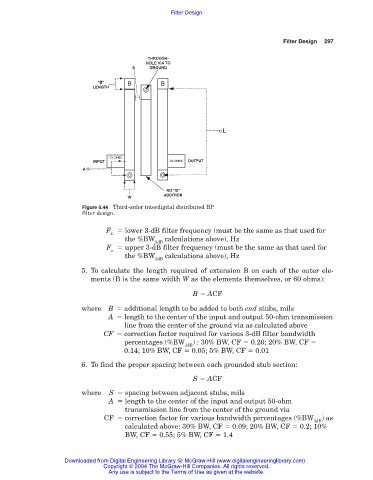
Figure 6.44 Third-order interdigital distributed BP
filter design.
F lower 3-dB filter frequency (must be the same as that used for
L
the %BW calculations above), Hz
3dB
F upper 3-dB filter frequency (must be the same as that used for
u
the %BW calculations above), Hz
3dB
5. To calculate the length required of extension B on each of the outer ele-
ments (B is the same width W as the elements themselves, or 60 ohms):
B ACF
where B additional length to be added to both end stubs, mils
A length to the center of the input and output 50-ohm transmission
line from the center of the ground via as calculated above
CF correction factor required for various 3-dB filter bandwidth
percentages (%BW ) : 30% BW, CF 0.20; 20% BW, CF
3dB
0.14; 10% BW, CF 0.05; 5% BW, CF 0.01
6. To find the proper spacing between each grounded stub section:
S ACF
where S spacing between adjacent stubs, mils
A length to the center of the input and output 50-ohm
transmission line from the center of the ground via
CF correction factor for various bandwidth percentages (%BW ) as
3dB
calculated above: 30% BW, CF 0.09; 20% BW, CF 0.2; 10%
BW, CF 0.55; 5% BW, CF 1.4
Downloaded from Digital Engineering Library @ McGraw-Hill (www.digitalengineeringlibrary.com)
Copyright © 2004 The McGraw-Hill Companies. All rights reserved.
Any use is subject to the Terms of Use as given at the website.