
Page 300 - Complete Wireless Design
P. 300
Filter Design
Filter Design 299
Both the bottom and top ground plane of a PCB should be connected together
by through-hole vias in order to form a continuous ground plane, since most
microwave circuits will have not only this bottom layer, but also a top ground
plane around the circuit or filter structure itself, which covers most of the bare
top surface area with copper. The top layer assists in reducing EMI and field
coupling and produces better heat dissipation and grounding.
Distributed (and lumped) filters can become detuned if a hand is placed near
to the circuit, or a cover or other conductive material is located closer than
designed. This is due to proximity effects, and must be considered when a dis-
tributed design is synthesized or built. All high-end microwave simulator pro-
grams are able to take this into account by permitting the engineer to set the
distance that the metal shield (“box”) will be above and to the side of the cir-
cuit or filter.
6.3 Diplexer Filters
6.3.1 Introduction
Diplexers are two or more combined filters in a single package that are adopted
to separate two or more different frequencies. This concept can be employed to
separate the transmit from the receive frequency in a frequency division duplex
(FDD) transceiver, in which application it is sometimes referred to as a duplexer.
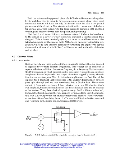
A diplexer also can be placed at the output of a mixer stage (Fig. 6.46), where it
functions as an absorptive filter. In this mixer application, the first filter of the
diplexer has a passband that corresponds to the undesired frequencies, so these
pass right through and are then terminated into a 50-ohm load. These same
undesired frequencies are blocked from entering the second filter by the filter’s
own stopband, but its passband passes the desired signals onto the IF sections
of the receiver. Thus, the undesired signals through the first filter are absorbed,
instead of reflected, because they are properly terminated into the 50-ohm resis-
tive load. This will prevent any undesired frequency products—created by mix-
er nonlinearities—from being bounced off a standard filter’s reflective stopband
and returning to the mixer, causing increased IMD levels.
Figure 6.46 A BPF diplexer placed at the output of a conversion stage to decrease IMD.
Downloaded from Digital Engineering Library @ McGraw-Hill (www.digitalengineeringlibrary.com)
Copyright © 2004 The McGraw-Hill Companies. All rights reserved.
Any use is subject to the Terms of Use as given at the website.