
Page 296 - Complete Wireless Design
P. 296
Filter Design
Filter Design 295
11,800
f
where wavelength of the frequency of interest (f) , mils
11,800 the numerical value required to obtain a in mils while
using an f in GHz
f frequency of the signal of interest, GHz
d. Multiply the resultant velocity of propagation (V ) by one-quarter the
P
wavelength of the signal in order to arrive at the quarter-wavelength
of the signal of interest (in mils) when it is placed into the microstrip:
/4 (in mils) V /4
P
An open-stub bandstop filter (Fig. 6.43). A bandstop filter, being basically a
reversed bandpass filter, is also easy to design. Simply duplicate the above
bandpass design procedures, but leave the stub open instead of grounding it
through a via. Because it is now an open stub, however, the end effect will
demand that the length of the stub be trimmed down by approximately 5 per-
cent below the calculated length: Cut a small amount off the end of the open
stub until the center frequency is as desired (not all electromagnetic
microwave simulation software packages will take the end effect into
account).
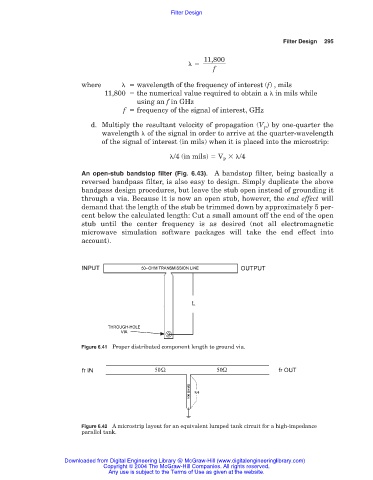
Figure 6.41 Proper distributed component length to ground via.
Figure 6.42 A microstrip layout for an equivalent lumped tank circuit for a high-impedance
parallel tank.
Downloaded from Digital Engineering Library @ McGraw-Hill (www.digitalengineeringlibrary.com)
Copyright © 2004 The McGraw-Hill Companies. All rights reserved.
Any use is subject to the Terms of Use as given at the website.