
Page 420 - Complete Wireless Design
P. 420
Wireless Issues
Wireless Issues 419
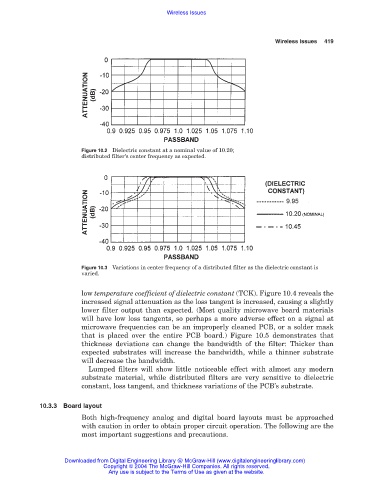
Figure 10.2 Dielectric constant at a nominal value of 10.20;
distributed filter’s center frequency as expected.
Figure 10.3 Variations in center frequency of a distributed filter as the dielectric constant is
varied.
low temperature coefficient of dielectric constant (TCK). Figure 10.4 reveals the
increased signal attenuation as the loss tangent is increased, causing a slightly
lower filter output than expected. (Most quality microwave board materials
will have low loss tangents, so perhaps a more adverse effect on a signal at
microwave frequencies can be an improperly cleaned PCB, or a solder mask
that is placed over the entire PCB board.) Figure 10.5 demonstrates that
thickness deviations can change the bandwidth of the filter: Thicker than
expected substrates will increase the bandwidth, while a thinner substrate
will decrease the bandwidth.
Lumped filters will show little noticeable effect with almost any modern
substrate material, while distributed filters are very sensitive to dielectric
constant, loss tangent, and thickness variations of the PCB’s substrate.
10.3.3 Board layout
Both high-frequency analog and digital board layouts must be approached
with caution in order to obtain proper circuit operation. The following are the
most important suggestions and precautions.
Downloaded from Digital Engineering Library @ McGraw-Hill (www.digitalengineeringlibrary.com)
Copyright © 2004 The McGraw-Hill Companies. All rights reserved.
Any use is subject to the Terms of Use as given at the website.