
Page 429 - Complete Wireless Design
P. 429
Wireless Issues
428 Chapter Ten
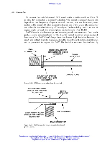
To connect the radio’s internal PCB board to the outside world, an SMA, N,
or BNC RF connector is normally adopted. The actual connector chosen will
depend on the frequency of operation and the cost, and can be directly con-
nected to the board’s 50-ohm microstrip line in one of two ways. The connector
can either be launched directly off the edge of the board (Fig. 10.12), or at a 90
degree angle through the ground plane and substrate (Fig. 10.13).
SAW filters in wireless design are becoming much more common than in the
past, so some considerations for the board’s layout must be accommodated.
Because of the SAW filter’s large insertion losses, high isolation between its
input and output must be maintained on the circuit board, since a signal must
not be permitted to bypass the SAW. The isolation required is calculated by
Figure 10.12 SMD connector edge-board-mounted.
Figure 10.13 SMD connector board-mounted on top of
ground plane.
Downloaded from Digital Engineering Library @ McGraw-Hill (www.digitalengineeringlibrary.com)
Copyright © 2004 The McGraw-Hill Companies. All rights reserved.
Any use is subject to the Terms of Use as given at the website.