
Page 140 - Compression Machinery for Oil and Gas
P. 140
Centrifugal Compressors Chapter 3 127
Lower flow impellers T R: Recycle
50,000 T: Speed topping
C: Choke
45,000 Add impellers D: Decreased speed
40,000 R
35,000
Head or pressure ratio
30,000 75% 73%
25,000 71%
20,000 D C 14,500 15,500 rpm
15,000 Remove impellers 11,500 12,500 13,500
10,000 9500 rpm 10,500 Higher flow impellers
5000
Actual inlet flow
0
50 100 150 200 250 300 350 400
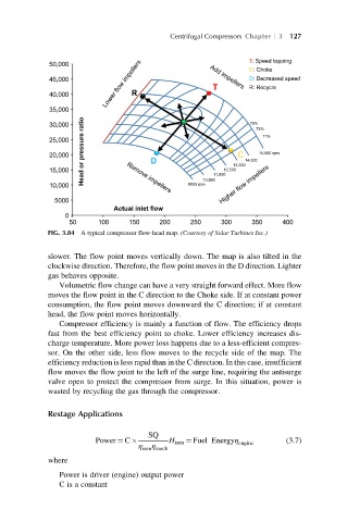
FIG. 3.84 A typical compressor flow-head map. (Courtesy of Solar Turbines Inc.)
slower. The flow point moves vertically down. The map is also tilted in the
clockwise direction. Therefore, the flow point moves in the D direction. Lighter
gas behaves opposite.
Volumetric flow change can have a very straight forward effect. More flow
moves the flow point in the C direction to the Choke side. If at constant power
consumption, the flow point moves downward the C direction; if at constant
head, the flow point moves horizontally.
Compressor efficiency is mainly a function of flow. The efficiency drops
fast from the best efficiency point to choke. Lower efficiency increases dis-
charge temperature. More power loss happens due to a less-efficient compres-
sor. On the other side, less flow moves to the recycle side of the map. The
efficiency reduction is less rapid than in the C direction. In this case, insufficient
flow moves the flow point to the left of the surge line, requiring the antisurge
valve open to protect the compressor from surge. In this situation, power is
wasted by recycling the gas through the compressor.
Restage Applications
SQ
Power ¼ C H isen ¼ Fuel Energyη engine (3.7)
η
η isen mech
where
Power is driver (engine) output power
C is a constant