
Page 141 - Compression Machinery for Oil and Gas
P. 141
128 SECTION II Types of Equipment
SQ is standard flow
η mech is mechanical efficiency
η engine is engine efficiency
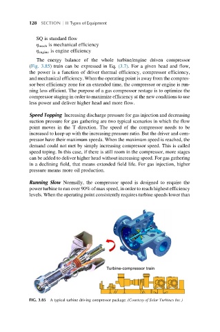
The energy balance of the whole turbine/engine driven compressor
(Fig. 3.85) train can be expressed in Eq. (3.7). For a given head and flow,
the power is a function of driver thermal efficiency, compressor efficiency,
and mechanical efficiency. When the operating point is away from the compres-
sor best efficiency zone for an extended time, the compressor or engine is run-
ning less efficient. The purpose of a gas compressor restage is to optimize the
compressor staging in order to maximize efficiency at the new conditions to use
less power and deliver higher head and more flow.
Speed Topping Increasing discharge pressure for gas injection and decreasing
suction pressure for gas gathering are two typical scenarios in which the flow
point moves in the T direction. The speed of the compressor needs to be
increased to keep up with the increasing pressure ratio. But the driver and com-
pressor have their maximum speeds. When the maximum speed is reached, the
demand could not met by simply increasing compressor speed. This is called
speed toping. In this case, if there is still room in the compressor, more stages
can be added to deliver higher head without increasing speed. For gas gathering
in a declining field, that means extended field life. For gas injection, higher
pressure means more oil production.
Running Slow Normally, the compressor speed is designed to require the
power turbine to run over 90% of max speed, in order to reach highest efficiency
levels. When the operating point consistently requires turbine speeds lower than
FIG. 3.85 A typical turbine driving compressor package. (Courtesy of Solar Turbines Inc.)