
Page 195 - Compression Machinery for Oil and Gas
P. 195
184 SECTION II Types of Equipment
2A
P 3
D
2
Pressure
P 4 1
S
4A
0 V V V
3 4 1
Volume
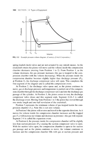
FIG. 5.2 Example pressure-volume diagram. (Courtesy of Ariel Corporation.)
spring-loaded check valves and are not actuated by any outside means. As the
crankshaft rotates the piston will move and the volume inside the compression
chamber decreases (moving from Position 1 to 2). From Position 1, as the
volume decreases, the gas pressure increases (the gas is trapped in the com-
pression chamber with the volume decreasing). When the pressure inside the
compression chamber becomes slightly higher than discharge pressure (P D ,
at Position 2), the discharge compressor valve will open. This completes the
first segment of the diagram and is called the compression event.
At Position 2, the discharge valve opens and, as the piston continues to
move, gas at discharge pressure and temperature is pushed out of the compres-
sion chamber through the discharge compressor valve and into the discharge gas
passage of the cylinder. At Position 3, the piston comes to rest, the discharge
compressor valve closes and this segment ends. Segment 2-2A-3 is called
the discharge event. Moving from Position 1 to 3 the piston has moved through
one stroke length and one-half revolution of the crankshaft.
Position 3 represents the minimum volume of gas trapped inside the com-
pression chamber (V 3 ). Note this is not zero volume.
At Position 3 the piston will reverse and travel in the opposite direction. As it
moves the volume inside the compression chamber increases and the trapped
gas (V 3 ) will increase in volume and decrease in pressure—the gas will expand.
Segment 3-4 is called the expansion event.
At Position 4, the pressure inside the compression chamber will be slightly
less than suction pressure (P S ) causing the suction compressor valve to open.
With the suction valve open, the compression chamber is open to the suction
gas passage and as the piston continues to move, the volume continues to
increase and the compression chamber fills with gas at suction pressure and