
Page 200 - Compression Machinery for Oil and Gas
P. 200
Reciprocating Compressors Chapter 5 189
8
x v p ffiffiffiffiffiffiffiffiffiffiffiffiffiffiffiffiffiffiffiffiffiffiffi
>
> 2ρ P s Pð Þ for P s > P
C d,v A F,v
> s
<
x v,max
_ m s ¼ (5.5)
x v p ffiffiffiffiffiffiffiffiffiffiffiffiffiffiffiffiffiffiffiffiffi
>
> 2ρ P P s Þ for P s < P
> C d,v A F,v ð
:
x v,max
8
x v p ffiffiffiffiffiffiffiffiffiffiffiffiffiffiffiffiffiffiffiffiffiffi
>
ð
C d,v A F,v for P > P d
> 2ρ P P d Þ
>
<
x v,max
_ m d ¼ (5.6)
x v p ffiffiffiffiffiffiffiffiffiffiffiffiffiffiffiffiffiffiffiffiffiffiffiffi
>
2ρ P d Pð
>
> C d,v A F,v d Þ for P < P d
:
x v,max
Simulation and Example Performance Plots
System Model
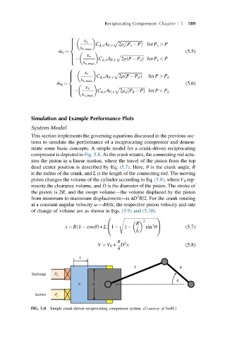
This section implements the governing equations discussed in the previous sec-
tions to simulate the performance of a reciprocating compressor and demon-
strate some basic concepts. A simple model for a crank-driven reciprocating
compressor is depicted in Fig. 5.8. As the crank rotates, the connecting rod actu-
ates the piston in a linear motion, where the travel of the piston from the top
dead center position is described by Eq. (5.7). Here, θ is the crank angle, R
is the radius of the crank, and L is the length of the connecting rod. The moving
piston changes the volume of the cylinder according to Eq. (5.8), where V 0 rep-
resents the clearance volume, and D is the diameter of the piston. The stroke of
the piston is 2R, and the swept volume—the volume displaced by the piston
2
from minimum to maximum displacement—is πD R/2. For the crank rotating
at a constant angular velocity ω¼dθ/dt, the respective piston velocity and rate
of change of volume are as shown in Eqs. (5.9) and (5.10).
0 ffiffiffiffiffiffiffiffiffiffiffiffiffiffiffiffiffiffiffiffiffiffiffiffiffiffiffiffiffiffiffi1
s
2
R
ð
x ¼ R 1 cosθÞ + L 1 1 sin θ (5.7)
@
2 A
L
π
2
V ¼ V 0 + D x (5.8)
4
FIG. 5.8 Simple crank-driven reciprocating compressor system. (Courtesy of SwRI.)