
Page 199 - Compression Machinery for Oil and Gas
P. 199
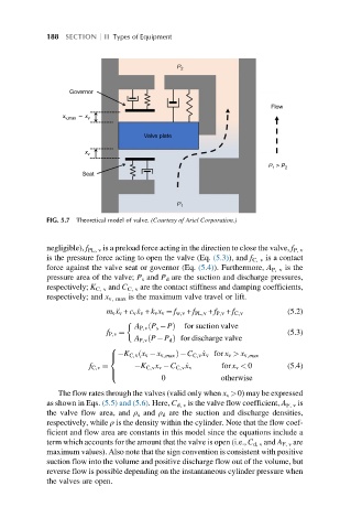
188 SECTION    II Types of Equipment


                  Governor                  P 2

                                                                    Flow
                x v,max –  x v

                                    Valve plate

                      x v

                     Seat                                          P 1  > P 2


                                            P 1
            FIG. 5.7 Theoretical model of valve. (Courtesy of Ariel Corporation.)


            negligible), f PL, v is a preload force acting in the direction to close the valve, f P, v
            is the pressure force acting to open the valve (Eq. (5.3)), and f C, v is a contact
            force against the valve seat or governor (Eq. (5.4)). Furthermore, A P, v is the
            pressure area of the valve; P s and P d are the suction and discharge pressures,
            respectively; K C, v and C C, v are the contact stiffness and damping coefficients,
            respectively; and x v, max is the maximum valve travel or lift.

                           m v € x v + c v _ x v + k v x v ¼ f w,v + f PL,v + f P,v + f C,v  (5.2)

                                  A P,v P s  Pð  Þ  for suction valve
                           f P,v ¼                                      (5.3)
                                  A P,v P P d Þ for discharge valve
                                     ð
                            8
                                   ð
                               K C,v x v  x v,max Þ C C,v _ x v for x v > x v,max
                            >
                            <
                       f C,v ¼     K C,v x v  C C,v _ x v  for x v < 0  (5.4)
                            >
                                         0             otherwise
                            :
               The flow rates through the valves (valid only when x v >0) may be expressed
            as shown in Eqs. (5.5) and (5.6). Here, C d, v is the valve flow coefficient, A F, v is
            the valve flow area, and ρ s and ρ d are the suction and discharge densities,
            respectively, while ρ is the density within the cylinder. Note that the flow coef-
            ficient and flow area are constants in this model since the equations include a
            term which accounts for the amount that the valve is open (i.e., C d, v and A F, v are
            maximum values). Also note that the sign convention is consistent with positive
            suction flow into the volume and positive discharge flow out of the volume, but
            reverse flow is possible depending on the instantaneous cylinder pressure when
            the valves are open.