
Page 198 - Compression Machinery for Oil and Gas
P. 198
Reciprocating Compressors Chapter 5 187
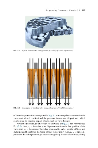
FIG. 5.5 Typical poppet valve configuration. (Courtesy of Ariel Corporation.)
FIG. 5.6 One degree of freedom valve model. (Courtesy of Ariel Corporation.)
of the valve plate travel are depicted in Fig. 5.7 with compliant structures for the
valve seat (closed position) and the governor (maximum lift position), which
can be used to simulate impact effects, such as valve bounce.
Newton’s Second Law of Motion for the valve of Fig. 5.7 can be written as
Eq. (5.2). Here, x v is the valve plate displacement from the free position of the
valve seat, m v is the mass of the valve plate, and k v and c v are the stiffness and
damping coefficients for the valve spring, respectively. Also, f w, v is the com-
ponent of the valve plate weight vector acting along the line of action (typically