
Page 206 - Compression Machinery for Oil and Gas
P. 206
Reciprocating Compressors Chapter 5 195
5
4
3
P /P s
2
1
0
0 45 90 135 180 225 270 315 360
Crank angle (degrees)
Mass flow: 4.95e–02 kg/s, Power: 73.2 kW, PV Eff: 71.0%
5
4
3
P/P s
2
1
0
1 1.5 2 2.5 V / V 0 3.5 4 4.5 5
3
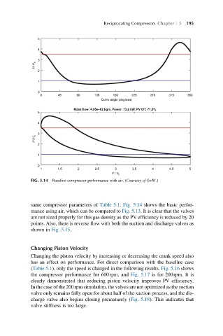
FIG. 5.14 Baseline compressor performance with air. (Courtesy of SwRI.)
same compressor parameters of Table 5.1. Fig. 5.14 shows the basic perfor-
mance using air, which can be compared to Fig. 5.13. It is clear that the valves
are not sized properly for this gas density as the PV efficiency is reduced by 20
points. Also, there is reverse flow with both the suction and discharge valves as
shown in Fig. 5.15.
Changing Piston Velocity
Changing the piston velocity by increasing or decreasing the crank speed also
has an effect on performance. For direct comparison with the baseline case
(Table 5.1), only the speed is changed in the following results. Fig. 5.16 shows
the compressor performance for 600rpm, and Fig. 5.17 is for 200rpm. It is
clearly demonstrated that reducing piston velocity improves PV efficiency.
In the case of the 200rpm simulation, the valves are not optimized as the suction
valve only remains fully open for about half of the suction process, and the dis-
charge valve also begins closing prematurely (Fig. 5.18). This indicates that
valve stiffness is too large.