
Page 209 - Compression Machinery for Oil and Gas
P. 209
198 SECTION II Types of Equipment
Reduced Valve Stiffness
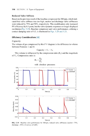
Based on the previous result of the baseline compressor for 200rpm, which indi-
cated that valve stiffness was too high, suction and discharge valve stiffnesses
were reduced by 75% and 50%, respectively. This modification only increased
PV efficiency by 0.1 point, but the valve dynamic responses no longer displayed
oscillation (Fig. 5.19). Baseline compressor and valve performance, utilizing a
contact damping ratio of 0.3, is illustrated in Figs. 5.20 and 5.21.
Efficiency Considerations [4]
Capacity
The volume of gas compressed by this P-V diagram is the difference in volume
between Positions 1 and 4:
Capacity ¼ V 1 V 4
This volume is influenced by the compression ratio (R C ) and the magnitude
of V 3 . Compression ratio is:
P D
R C ¼
P S
with absolute pressures
120
Suction
100
Discharge
Valve position (%) 60
80
40
20
0
–20
0 0.1 0.2 0.3 0.4 0.5 0.6 0.7
Time (s)
0.05
Suction
0.04
Discharge
Mass flow (kg/s) 0.03
0.02
0.01
0
–0.01
0 0.1 0.2 0.3 0.4 0.5 0.6 0.7
Time (s)
FIG. 5.19 Baseline valve performance for 200rpm, reduced valve stiffnesses (suction—75%,
discharge—50%). (Courtesy of SwRI.)