
Page 213 - Compression Machinery for Oil and Gas
P. 213
202 SECTION II Types of Equipment
P
D
Pressure
P
S
V V
0
3 V 4 1
Volume
FIG. 5.23 Pressure-volume showing “low” volumetric efficiency.
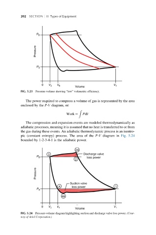
The power required to compress a volume of gas is represented by the area
enclosed by the P-V diagram, or:
Z
Work ¼ PdV
The compression and expansion events are modeled thermodynamically as
adiabatic processes, meaning it is assumed that no heat is transferred to or from
the gas during these events. An adiabatic thermodynamic process is an isentro-
pic (constant entropy) process. The area of the P-V diagram in Fig. 5.24
bounded by 1-2-3-4-1 is the adiabatic power.
2A
P 3 Discharge valve
D
loss power
2
Pressure
Suction valve
P 4 loss power 1
S
4A
V V
0 V 4
3 1
Volume
FIG. 5.24 Pressure-volume diagram highlighting suction and discharge valve loss power. (Cour-
tesy of Ariel Corporation.)