
Page 324 - Compression Machinery for Oil and Gas
P. 324
310 SECTION II Types of Equipment
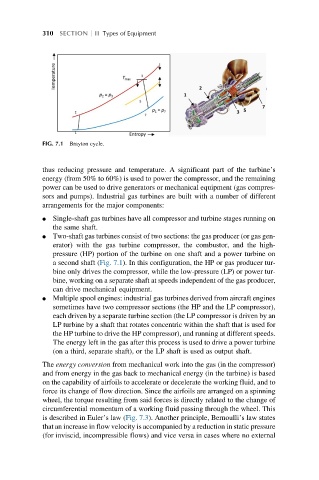
FIG. 7.1 Brayton cycle.
thus reducing pressure and temperature. A significant part of the turbine’s
energy (from 50% to 60%) is used to power the compressor, and the remaining
power can be used to drive generators or mechanical equipment (gas compres-
sors and pumps). Industrial gas turbines are built with a number of different
arrangements for the major components:
l Single-shaft gas turbines have all compressor and turbine stages running on
the same shaft.
l Two-shaft gas turbines consist of two sections: the gas producer (or gas gen-
erator) with the gas turbine compressor, the combustor, and the high-
pressure (HP) portion of the turbine on one shaft and a power turbine on
a second shaft (Fig. 7.1). In this configuration, the HP or gas producer tur-
bine only drives the compressor, while the low-pressure (LP) or power tur-
bine, working on a separate shaft at speeds independent of the gas producer,
can drive mechanical equipment.
l Multiple spool engines: industrial gas turbines derived from aircraft engines
sometimes have two compressor sections (the HP and the LP compressor),
each driven by a separate turbine section (the LP compressor is driven by an
LP turbine by a shaft that rotates concentric within the shaft that is used for
the HP turbine to drive the HP compressor), and running at different speeds.
The energy left in the gas after this process is used to drive a power turbine
(on a third, separate shaft), or the LP shaft is used as output shaft.
The energy conversion from mechanical work into the gas (in the compressor)
and from energy in the gas back to mechanical energy (in the turbine) is based
on the capability of airfoils to accelerate or decelerate the working fluid, and to
force its change of flow direction. Since the airfoils are arranged on a spinning
wheel, the torque resulting from said forces is directly related to the change of
circumferential momentum of a working fluid passing through the wheel. This
is described in Euler’s law (Fig. 7.3). Another principle, Bernoulli’s law states
that an increase in flow velocity is accompanied by a reduction in static pressure
(for inviscid, incompressible flows) and vice versa in cases where no external