
Page 327 - Compression Machinery for Oil and Gas
P. 327
Drivers Chapter 7 313
Performance
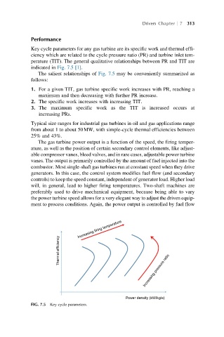
Key cycle parameters for any gas turbine are its specific work and thermal effi-
ciency which are related to the cycle pressure ratio (PR) and turbine inlet tem-
perature (TIT). The general qualitative relationships between PR and TIT are
indicated in Fig. 7.5 [1].
The salient relationships of Fig. 7.5 may be conveniently summarized as
follows:
1. For a given TIT, gas turbine specific work increases with PR, reaching a
maximum and then decreasing with further PR increase.
2. The specific work increases with increasing TIT.
3. The maximum specific work as the TIT is increased occurs at
increasing PRs.
Typical size ranges for industrial gas turbines in oil and gas applications range
from about 1 to about 50MW, with simple-cycle thermal efficiencies between
25% and 43%.
The gas turbine power output is a function of the speed, the firing temper-
ature, as well as the position of certain secondary control elements, like adjust-
able compressor vanes, bleed valves, and in rare cases, adjustable power turbine
vanes. The output is primarily controlled by the amount of fuel injected into the
combustor. Most single-shaft gas turbines run at constant speed when they drive
generators. In this case, the control system modifies fuel flow (and secondary
controls) to keep the speed constant, independent of generator load. Higher load
will, in general, lead to higher firing temperatures. Two-shaft machines are
preferably used to drive mechanical equipment, because being able to vary
the power turbine speed allows for a very elegant way to adjust the driven equip-
ment to process conditions. Again, the power output is controlled by fuel flow
Increasing firing temperature
Thermal efficiency
Increasing pressure ratio
Power density (kW/kg/s)
FIG. 7.5 Key cycle parameters.