
Page 331 - Compression Machinery for Oil and Gas
P. 331
316 SECTION II Types of Equipment
older than most people realize, yet its use in the automobile is so routine that
most take it for granted as part of their daily lives. It is a proven technology that
serves society effectively every day.
The reciprocating engine most commonly used in gas compression is a spark-
ignited internal combustion design fueled by the natural gas itself. The thermo-
dynamic theory involved is, at the basic level, no different than that for the tur-
bine:fuelandairarecombined,compressed,andignited,andtheexpansionofthe
burning gas is tapped to extract usable shaft work to power other processes, such
as the gas compressor at the back of the compressor package.
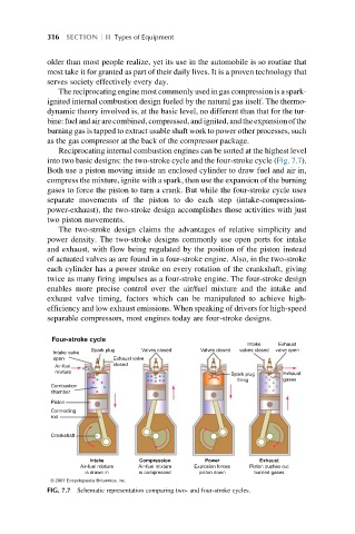
Reciprocating internal combustion engines can be sorted at the highest level
into two basic designs: the two-stroke cycle and the four-stroke cycle (Fig. 7.7).
Both use a piston moving inside an enclosed cylinder to draw fuel and air in,
compress the mixture, ignite with a spark, then use the expansion of the burning
gases to force the piston to turn a crank. But while the four-stroke cycle uses
separate movements of the piston to do each step (intake-compression-
power-exhaust), the two-stroke design accomplishes those activities with just
two piston movements.
The two-stroke design claims the advantages of relative simplicity and
power density. The two-stroke designs commonly use open ports for intake
and exhaust, with flow being regulated by the position of the piston instead
of actuated valves as are found in a four-stroke engine. Also, in the two-stroke
each cylinder has a power stroke on every rotation of the crankshaft, giving
twice as many firing impulses as a four-stroke engine. The four-stroke design
enables more precise control over the air/fuel mixture and the intake and
exhaust valve timing, factors which can be manipulated to achieve high-
efficiency and low exhaust emissions. When speaking of drivers for high-speed
separable compressors, most engines today are four-stroke designs.
Four-stroke cycle
Intake Exhaust
Spark plug Valves closed Valves closed valves closed valve open
Intake valve
open Exhaust valve
closed
Air-fuel
mixture
Exhaust
Spark plug
gases
firing
Combustion
chamber
Piston
Connecting
rod
Crankshaft
Intake Compression Power Exhaust
Air-fuel mixture Air-fuel mixture Explosion forces Piston pushes out
is drawn in is compressed piston down burned gases
© 2007 Encyclopædia Britannica, Inc.
FIG. 7.7 Schematic representation comparing two- and four-stroke cycles.