
Page 335 - Compression Machinery for Oil and Gas
P. 335
320 SECTION II Types of Equipment
P P
AG conv
τ w
Air-gap power
P = load m
out
τ w
ind m
P = √3 V I cos q
in T L
P
P P friction P stray
P RCL and windage ( misc.)
P core (rotor
SCL (core
copper
(stator
losses)
loss)
copper
loss)
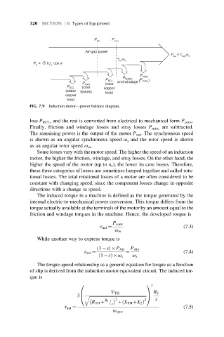
FIG. 7.9 Induction motor—power balance diagram.
loss P RCL , and the rest is converted from electrical to mechanical form P conv .
Finally, friction and windage losses and stray losses P misc are subtracted.
The remaining power is the output of the motor P out . The synchronous speed
is shown as an angular synchronous speed ω s and the rotor speed is shown
as an angular rotor speed ω m .
Some losses vary with the motor speed. The higher the speed of an induction
motor, the higher the friction, windage, and stray losses. On the other hand, the
higher the speed of the motor (up to n s ), the lower its core losses. Therefore,
these three categories of losses are sometimes lumped together and called rota-
tional losses. The total rotational losses of a motor are often considered to be
constant with changing speed, since the component losses change in opposite
directions with a change in speed.
The induced torque in a machine is defined as the torque generated by the
internal electric-to-mechanical power conversion. This torque differs from the
torque actually available at the terminals of the motor by an amount equal to the
friction and windage torques in the machine. Hence, the developed torque is
P conv
τ ind ¼ (7.3)
ω m
While another way to express torque is
ð 1 sÞ P AG P AG
τ ind ¼ ¼ (7.4)
ð 1 sÞ ω s ω s
The torque-speed relationship as a general equation for torque as a function
of slip is derived from the induction motor equivalent circuit. The induced tor-
que is
0 1 2
V TH C R 2
B
3 q
@ ffiffiffiffiffiffiffiffiffiffiffiffiffiffiffiffiffiffiffiffiffiffiffiffiffiffiffiffiffiffiffiffiffiffiffiffiffiffiffiffiffiffiffiffiffiffiffiffiffiffiffiffiffiA
2 2 s
R TH + = s + X TH + X 2 Þ
R 2
ð
τ ind ¼ (7.5)
ω sync