
Page 339 - Compression Machinery for Oil and Gas
P. 339
324 SECTION II Types of Equipment
200
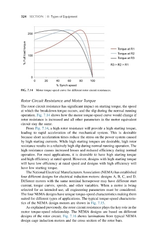
% Full load torque 100 Torque at R1
Torque at R2
Torque at R3
R3 > R2 > R1
0
0 20 40 60 80 100
% Synch speed
FIG. 7.14 Motor torque-speed curve for different rotor circuit resistances.
Rotor Circuit Resistance and Motor Torque
The rotor circuit resistance has significant impact on starting torque, the speed
at which the breakdown torque occurs, and the slip during the normal running
operation. Fig. 7.14 shows how the motor torque-speed curve would change if
rotor resistance is increased and all other parameters in the motor equivalent
circuit stay the same.
From Fig. 7.14, a high rotor resistance will provide a high starting torque,
leading to rapid acceleration of the mechanical system. This is desirable
because short acceleration times reduce the stress on the power system caused
by high starting currents. While high starting torques are desirable, high rotor
resistance results in a relatively high slip during normal running operation. The
high resistance causes increased losses and reduced efficiency during normal
operation. For most applications, it is desirable to have high starting torque
and high efficiency at rated speed. However, designs with high starting torque
will have low efficiency at rated speed and designs with high efficiency will
have low starting torque.
The National Electrical Manufacturers Association (NEMA) has established
four different designs for electrical induction motors: designs A, B, C, and D.
Different motors with the same nominal horsepower may have different start
current, torque curves, speeds, and other variables. When a motor is being
selected for an intended use, all engineering parameters must be considered.
The four NEMA designs have unique torque-speed characteristics making them
suited for different types of applications. The typical torque-speed characteris-
tics of the NEMA design motors are shown in Fig. 7.15.
As explained previously, the rotor circuit resistance plays the key role in the
motor torque-speed relationship. The NEMA designs are based on different
designs of the rotor circuit. Fig. 7.16 shows laminations from typical NEMA
design cage induction motors and the cross section of the rotor bars.