
Page 343 - Compression Machinery for Oil and Gas
P. 343
328 SECTION II Types of Equipment
At each revolution, the reciprocating components are accelerated and decel-
erated as the pistons travels out to the outer end and back to the inboard end of
the stroke. In addition, the gas is compressed, discharged, and then expanded on
the first part of the reversed stroke. This implies a severe torque pulsation which
on a two- and four-throw compressor will include a peak torque that will usually
exceed 200% of the mean torque and a torque reversed for part of each revo-
lution. A six-throw is not as extreme but still has a severe pulsating torque. This
torque pulsation is partially absorbed by the inertia of the flywheel (when pre-
sent) and also by the motor inertia so as to reduce the torque variation that must
be provided by the motor magnetic field.
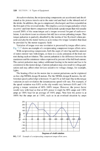
Variation of torque over one revolution is presented by torque effort curve.
Fig. 7.17 shows an example of a reciprocating compressor torque effort curve.
With reciprocating compressors, both the angle of rotor lag and the amount
of stator current vary with torque, so there is a cyclic pulsation of the load cur-
rent during each revolution. The current pulsation is the difference between the
maximum and the minimum values expressed in percent of the full load current.
The current pulsation may induce additional heating in the motor and has to be
considered in the motor design. Current pulsation may also result in voltage pul-
sation and may affect other devices sensitive to voltage change, for example,
lights.
The heating effect on the motor due to current pulsations can be explained
on low slip NEMA design B motors. For the NEMA design B motors, the dif-
ferential speed (called slip) is between 1% and 2% at full load. Due to the torque
variation at each revolution the instantaneous speed will vary. For example, if
the speed variation was 0.8% so the slip would vary between 0.6% and 1.4%
giving a torque variation of 60%–140% torque. However, the power factor
would vary with load so that at 60% power it might be 80% amps and 140%
amps at 140% load for an average of 110% amps. Note how the power is at
100% but the amps are at 110%, such as in an overload situation by amps
250
200
150
100
% Torque 50 0
–50 0
–100 40 80 120 160 200 240 280 320 360
–150
–200
–250
Degrees of shaft rotation
FIG. 7.17 Example of a reciprocating compressor torque effort curve.