
Page 336 - Compression Machinery for Oil and Gas
P. 336
Drivers Chapter 7 321
where V TH , R TH , and X TH are the Thevenin equivalents of voltage, resistance,
and reactance derived from the induction motor equivalent circuit and R 2 and X 2
are the rotor resistance and reactance.
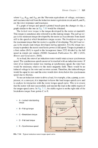
If a graph of torque and speed is plotted based upon the changes in slip, a
graph similar to the one in Fig. 7.10 would be obtained.
The locked rotor torque is the torque developed by the motor at standstill.
This torque is sometimes also referred to as the starting torque. The pull up tor-
que is the minimum torque developed by the motor as it accelerates from stand-
still to the speed at which breakdown torque occurs. The breakdown torque is
the maximum torque that the motor is capable of developing. The full load tor-
que is the steady-state torque developed during operation. It is the torque nec-
essary to produce the motor rated horse power at full speed. Torque in pounds at
a foot radius (lbft) is equal to the horsepower times 5252 divided by the full
speed in rounds per minute (NEMA Standards Publication No. MG 1-2016,
Motors and Generators, 2016).
At no load, the rotor of an induction motor would rotate at near synchronous
speed. The synchronous speed can never be reached with an induction motor. If
rotor of an induction motor was rotating at synchronous speed, the rotor bars
would be stationary relative to the stator magnetic field. There would be no
induced voltage in the rotor and no rotor current. Therefore, the induced torque
would be equal to zero and the rotor would slow down below the synchronous
speed due to friction.
To use an induction motor to drive a load, for example, a fan, a pump, a com-
pressor, or a conveyer, it is important to know the load torque-speed curve and
to analyze its interaction with the motor torque-speed curve. This is to ensure
that the motor will start successfully and operate the load in the stable region of
the torque-speed curve. In Fig. 7.11, the stable region is on the right side of the
breakdown torque from points C to E.
Breakdown
A – Locked rotor/starting torque
Locked rotor torque
(pullout)
torque
(starting torque) C
Percent of full-load torque A
B – Pull-up torque 200 Pull-up torque
(pull-in)
C – Breakdown torque 100 B D
D – Full load torque Full-load torque
No-load speed
E – Synchronous speed
E
0
0 50 100
Percent of synchronous speed
FIG. 7.10 Typical induction motor torque-speed curve.