
Page 333 - Compression Machinery for Oil and Gas
P. 333
318 SECTION II Types of Equipment
accumulated time during which the installation must be stopped to conduct rou-
tine maintenance. Gas engines require scheduled stoppages to inspect and/or
replace the spark plugs and to change the oil and filters. Other required adjust-
ments or component servicing can be performed less frequently, but still do fac-
tor into the overall owning and operating costs of the engine. Effective
operating strategies seek to extend these servicing intervals as much as possible
without risking component failures.
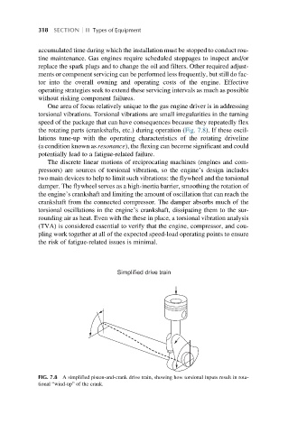
One area of focus relatively unique to the gas engine driver is in addressing
torsional vibrations. Torsional vibrations are small irregularities in the turning
speed of the package that can have consequences because they repeatedly flex
the rotating parts (crankshafts, etc.) during operation (Fig. 7.8). If these oscil-
lations tune-up with the operating characteristics of the rotating driveline
(a condition known as resonance), the flexing can become significant and could
potentially lead to a fatigue-related failure.
The discrete linear motions of reciprocating machines (engines and com-
pressors) are sources of torsional vibration, so the engine’s design includes
two main devices to help to limit such vibrations: the flywheel and the torsional
damper. The flywheel serves as a high-inertia barrier, smoothing the rotation of
the engine’s crankshaft and limiting the amount of oscillation that can reach the
crankshaft from the connected compressor. The damper absorbs much of the
torsional oscillations in the engine’s crankshaft, dissipating them to the sur-
rounding air as heat. Even with the these in place, a torsional vibration analysis
(TVA) is considered essential to verify that the engine, compressor, and cou-
pling work together at all of the expected speed-load operating points to ensure
the risk of fatigue-related issues is minimal.
Simplified drive train
FIG. 7.8 A simplified piston-and-crank drive train, showing how torsional inputs result in rota-
tional “wind-up” of the crank.