Page 379 - Compression Machinery for Oil and Gas
P. 379

360 SECTION    II Types of Equipment


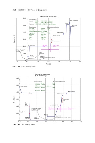
                                      Example cold startup curve
                      6000
                            Critical speeds
                                                                Check overspeed trip
                            Lateral  2SQV9  2900 - 3000 rpm (calc.)
                                 5M6-4  2600 - 2800 rpm (calc.)
                                                            MCS
                            Torsional  1254, 11852, 14599, 25146 rpm Calculated
                      5000
                                                                  Rated speed
                            Speed values    Min. required hold period
                            Low idle#1  500 rpm  10 min
                                      2000 rpm  120 min
                            Low idle#2
                            Critical speed band  2400 - 3200 rpm
                      4000                           Minimum speed
                                      3600 rpm
                            High idle#1     70 min
                            Min speed  3856 rpm  High idle speed
              Speed (rpm)  3000  OVS  5567 rpm   Critical speed band
                            MCS
                                      5061 rpm
                                      4820 rpm
                            Rated
                          Low idle speed #2      Governor valve
                                        T&T valve
                                                 control
                      2000
                                        control
               Establish light vacuum
               by enabling ejectors.
               Then, open TTV
                                     Check
                      1000           manual trip
                            Low idle
                                      Enable GC
                            speed #1
                                      supply seal steam increase vacuum
                        0
               –1.0      0.0      1.0       2.0       3.0      4.0       5.0
                                           Time (h)
            FIG. 7.47 Cold start-up curve.
                                 Example hot startup curve
                                 (5–30 min after trip)
               6000
                                0  Speed values  Min. required hold period
                                 Low idle#1  500 rpm  5 min
                                 Low idle#2  2000 rpm  2 min
               5000
                                 Critical speed band
                                         2400 - 3200 rpm
                   Check process
                                                 3 min
                                 High idle#1  3600 rpm
                                 Min speed  3856 rpm
                                                               Minimum speed
               4000
                            Stop
                                                     High idle speed
              Speed (rpm)  3000                           Critical speed
                                                          band
                        Stop
                        seal
                                               Low idle speed #2
                        steam
               2000
                                             T&T valve         Governor valve
                              Establish light vacuum
                                             control           control
                              by enabling ejectors.
                              Then, open TTV
                   Disable GC
               1000
                                         Low idle
                                         speed #1
                                                    Enable GC
                                                    supply seal steam increase vacuum
                        Break SC  Restart
                                preparation
                        vacuum
                 0
                  0.0     0.1     0.2     0.3     0.4     0.5    0.6     0.7
             FIG. 7.48 Hot start-up curve.
   374   375   376   377   378   379   380   381   382   383   384