
Page 382 - Compression Machinery for Oil and Gas
P. 382
Drivers Chapter 7 363
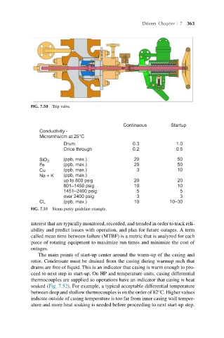
FIG. 7.50 Trip valve.
Continuous Startup
Conductivity -
Micromhs/cm at 25°C
Drum 0.3 1.0
Once through 0.2 0.5
(ppb, max.) 20 50
SiO
2
(ppb, max.) 20 50
Fe
10
Cu (ppb, max.) 3
(ppb, max.)
Na + K
up to 800 psig 20 20
801–1450 psig 10 10
1451–2400 psig 5 5
over 2400 psig 3 3
CL (ppb, max.) 10 10–30
FIG. 7.51 Steam purity guideline example.
interest that are typically monitored, recorded, and trended in order to track reli-
ability and predict issues with operation, and plan for future outages. A term
called mean time between failure (MTBF) is a metric that is analyzed for each
piece of rotating equipment to maximize run times and minimize the cost of
outages.
The main points of start-up center around the warm-up of the casing and
rotor. Condensate must be drained from the casing during warmup such that
drains are free of liquid. This is an indicator that casing is warm enough to pro-
ceed to next step in start-up. On HP and temperature units, casing differential
thermocouples are supplied so operations have an indicator that casing is heat
soaked (Fig. 7.52). For example, a typical acceptable differential temperature
between deep and shallow thermocouples is on the order of 82°C. Higher values
indicate outside of casing temperature is too far from inner casing wall temper-
ature and more heat soaking is needed before proceeding to next start-up step.