
Page 218 - Computational Fluid Dynamics for Engineers
P. 218
206 6. Inviscid Flow Equations for Incompressible Flows
C ELEMENTS OF W-VECTOR, SEE EQ. (4.5.21a)
6-2. Repeat Problem 6.1 by using the accelerated Gauss-Seidel method dis-
cussed in subsection 4.5.2. Assume that the initial solution is given by
/
2
i(l-» ) cosh( v 3//)^
cosh(V3//)L
6-3. Repeat Problem 6.1 by using the ADI method of subsection 4.5.2. Take
u = 0.05.
6-4. The NACA 0012 airfoil is a conventional airfoil which has a favorable
pressure distribution on the upper surface up to about a quarter chord point
at a = 0°; with increasing incidence angle, say a = 8°, the gradient becomes
unfavorable over practically the entire surface.
(a) Compute the pressure distribution on this airfoil with the panel program of
Section 6.5 for angles of attack of a = 0°, 4°, 10° and plot C p vs x/c and VjV^
vs x/c for each a.
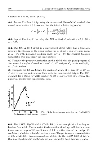
(b) Compute the lift coefficients for angles of attack of a from 0° to 20° at
4° degree intervals and compare them with the experimental data in Fig. P6.1
6
obtained for a chord Reynolds number R c (= VOQC/V) of 6 x 10 . Discuss the
numerical results with experimental data.
1.6
5 1.2
e
o
*S 0.4
o 8 16 24 32 Fig. P6.1. Experimental data for the NACA 0012
Section angle of attack a 0, deg. airfoil.
6-5. The NACA 65 3-018 airfoil (Table P6.1) is an example of a low drag or
laminar flow airfoil. The subscript 3 indicates that the drag coefficient is a min-
imum over a range of lift coefficients of 0.3 on either side of the design lift
coefficient, which for this airfoil section is zero. The performance characteristics
of this airfoil differ from a conventional airfoil, like the NACA 0012 airfoil, in
that near the design lift coefficient, the low-drag airfoil has a laminar boundary