
Page 232 - Computational Modeling in Biomedical Engineering and Medical Physics
P. 232
Magnetic stimulation and therapy 221
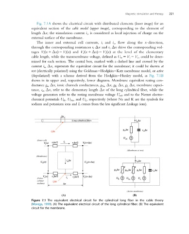
Fig. 7.1A shows the electrical circuit with distributed elements (lower image) for an
equivalent section of the cable model (upper image), corresponding to the element of
length Δx; the stimulation current i s , is considered as local injection of charge on the
external surface of the membrane.
The inner and external cell currents, i i and i e , flow along the x-direction,
through the corresponding resistances r i Δx and r e Δx drive the corresponding vol-
tages V i x 1 Δxð Þ 2 V i xðÞ and V e x 1 ΔxÞ 2 V e xðÞ at the level of the elementary
ð
cablelength, whilethe transmembranevoltage,defined as U m 5 V i 2 V e , could be deter-
mined for each section. The central box, marked with a dashed line and crossed by the
current i m Δx, represents the equivalent circuit for the membrane; it could be shown at
rest (electrically polarized) using the Goldman Hodgkin Katz membrane model, or active
(depolarized) with a scheme derived from the Hodgkin Huxley model, as Fig. 7.1B
shows in its upper and, respectively, lower diagrams. Membrane equivalent resting con-
ductance g m Δx, ionic channels conductances, g Na Δx, g K Δx, g L Δx, membrane capaci-
tance, c m Δx, refer to the elementary length Δx of the long cylindrical fiber, while the
voltage generators refer to the resting membrane voltage U m0 and to the Nernst electro-
chemical potentials U K , U Na ,and U L , respectively (where Na and K are the symbols for
sodium and potassium ions and L comes from the less significant Leakage ions).
Figure 7.1 The equivalent electrical circuit for the cylindrical long fiber in the cable theory
(Morega, 1999). (A) The equivalent electrical circuit of the long cylindrical fiber. (B) The equivalent
circuit for the membrane.