
Page 32 - Computational Retinal Image Analysis
P. 32
22 CHAPTER 3 The physics, instruments and modalities of retinal imaging
challenge is to prevent reflections of illumination at the cornea and lens surfaces (the
Purkinje reflections) since these can greatly reduce contrast of images or introduce
strong reflection artifacts. The strategies used vary between the main modalities:
fundus cameras, laser scanning ophthalmoscopes, indirect ophthalmoscopes and slit-
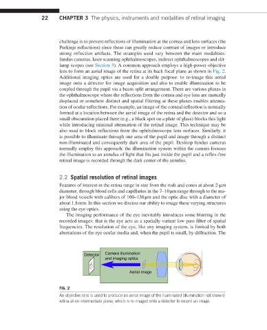
lamp scopes (see Section 3). A common approach employs a high-power objective
lens to form an aerial image of the retina at its back focal plane as shown in Fig. 2.
Additional imaging optics are used for a double purpose: to re-image this aerial
image onto a detector for image acquisition and also to enable illumination to be
coupled through the pupil via a beam-split arrangement. There are various planes in
the ophthalmoscope where the reflections from the cornea and eye lens are mutually
displaced or somehow distinct and spatial filtering at these planes enables attenua-
tion of ocular reflections. For example, an image of the corneal reflection is normally
formed at a location between the aerial image of the retina and the detector and so a
small obscuration placed there (e.g., a black spot on a plate of glass) blocks this light
while introducing minimal attenuation of the retinal image. This technique may be
also used to block reflections from the ophthalmoscope lens surfaces. Similarly, it
is possible to illuminate through one area of the pupil and image through a distinct
non-illuminated and consequently dark area of the pupil. Desktop fundus cameras
normally employ this approach: the illumination system within the camera focuses
the illumination to an annulus of light that fits just inside the pupil and a reflex-free
retinal image is recorded through the dark center of the annulus.
2.2 Spatial resolution of retinal images
Features of interest in the retina range in size from the rods and cones at about 2-μm
diameter, through blood cells and capillaries in the 7–10 μm range through to the ma-
jor blood vessels with calibers of 100–130 μm and the optic disc with a diameter of
about 1.8 mm. In this section we discuss our ability to image these varying structures
using the eye optics.
The imaging performance of the eye inevitably introduces some blurring in the
recorded images: that is the eye acts as a spatially-variant low-pass filter of spatial
frequencies. The resolution of the eye, like any imaging system, is limited by both
aberrations of the eye ocular media and, when the pupil is small, by diffraction. The
FIG. 2
An objective lens is used to produce an aerial image of the illuminated (illumination not shown)
retina at an intermediate plane, which is re-imaged onto a detector to record an image.