
Page 44 -
P. 44
2.1 / A BRIEF HISTORY OF COMPUTERS 21
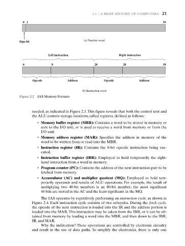
0 1 39
(a) Number word
Sign bit
Left instruction Right instruction
0 8 20 28 39
Opcode Address Opcode Address
(b) Instruction word
Figure 2.2 IAS Memory Formats
needed, as indicated in Figure 2.3. This figure reveals that both the control unit and
the ALU contain storage locations, called registers, defined as follows:
• Memory buffer register (MBR): Contains a word to be stored in memory or
sent to the I/O unit, or is used to receive a word from memory or from the
I/O unit.
• Memory address register (MAR): Specifies the address in memory of the
word to be written from or read into the MBR.
• Instruction register (IR): Contains the 8-bit opcode instruction being exe-
cuted.
• Instruction buffer register (IBR): Employed to hold temporarily the right-
hand instruction from a word in memory.
• Program counter (PC): Contains the address of the next instruction-pair to be
fetched from memory.
• Accumulator (AC) and multiplier quotient (MQ): Employed to hold tem-
porarily operands and results of ALU operations. For example, the result of
multiplying two 40-bit numbers is an 80-bit number; the most significant
40 bits are stored in the AC and the least significant in the MQ.
The IAS operates by repetitively performing an instruction cycle, as shown in
Figure 2.4. Each instruction cycle consists of two subcycles. During the fetch cycle,
the opcode of the next instruction is loaded into the IR and the address portion is
loaded into the MAR. This instruction may be taken from the IBR, or it can be ob-
tained from memory by loading a word into the MBR, and then down to the IBR,
IR, and MAR.
Why the indirection? These operations are controlled by electronic circuitry
and result in the use of data paths. To simplify the electronics, there is only one