
Page 45 -
P. 45
22 CHAPTER 2 / COMPUTER EVOLUTION AND PERFORMANCE
Arithmetic-logic unit (ALU)
AC MQ
Input–
Arithmetic-logic
circuits output
equipment
MBR
Instructions
and data
IBR PC
Main
memory
IR MAR
M
Control • Control
circuits • signals
• Addresses
Program control unit
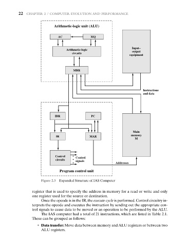
Figure 2.3 Expanded Structure of IAS Computer
register that is used to specify the address in memory for a read or write and only
one register used for the source or destination.
Once the opcode is in the IR,the execute cycle is performed.Control circuitry in-
terprets the opcode and executes the instruction by sending out the appropriate con-
trol signals to cause data to be moved or an operation to be performed by the ALU.
The IAS computer had a total of 21 instructions, which are listed in Table 2.1.
These can be grouped as follows:
• Data transfer: Move data between memory and ALU registers or between two
ALU registers.