
Page 167 -
P. 167
146 3 Image processing
procedure inverseWarp(f, h, out g):
For every pixel x in g(x )
ˆ
1. Compute the source location x = h(x )
2. Resample f(x) at location x and copy to g(x )
Algorithm 3.2 Inverse warping algorithm for creating an image g(x ) from an image f(x) using the parametric
transform x = h(x).
^
^ x=h(x’)
x=h(x’)
x f(x) x’ g(x’) x f(x) x’ g(x’)
(a) (b)
ˆ
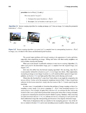
Figure 3.47 Inverse warping algorithm: (a) a pixel g(x ) is sampled from its corresponding location x = h(x )
in image f(x); (b) detail of the source and destination pixel locations.
The second major problem with forward warping is the appearance of cracks and holes,
especially when magnifying an image. Filling such holes with their nearby neighbors can
lead to further aliasing and blurring.
What can we do instead? A preferable solution is to use inverse warping (Algorithm 3.2),
where each pixel in the destination image g(x ) is sampled from the original image f(x)
(Figure 3.47).
ˆ
How does this differ from the forward warping algorithm? For one thing, since h(x )
is (presumably) defined for all pixels in g(x ), we no longer have holes. More importantly,
resampling an image at non-integer locations is a well-studied problem (general image inter-
polation, see Section 3.5.2) and high-quality filters that control aliasing can be used.
ˆ
Where does the function h(x ) come from? Quite often, it can simply be computed as the
inverse of h(x). In fact, all of the parametric transforms listed in Table 3.5 have closed form
solutions for the inverse transform: simply take the inverse of the 3 × 3 matrix specifying the
transform.
In other cases, it is preferable to formulate the problem of image warping as that of re-
ˆ
sampling a source image f(x) given a mapping x = h(x ) from destination pixels x to
source pixels x. For example, in optical flow (Section 8.4), we estimate the flow field as the
location of the source pixel which produced the current pixel whose flow is being estimated,
as opposed to computing the destination pixel to which it is going. Similarly, when correcting
for radial distortion (Section 2.1.6), we calibrate the lens by computing for each pixel in the
final (undistorted) image the corresponding pixel location in the original (distorted) image.
What kinds of interpolation filter are suitable for the resampling process? Any of the fil-
ters we studied in Section 3.5.2 can be used, including nearest neighbor, bilinear, bicubic, and