
Page 74 -
P. 74
2.1 Geometric primitives and transformations 53
(a) (b) (c)
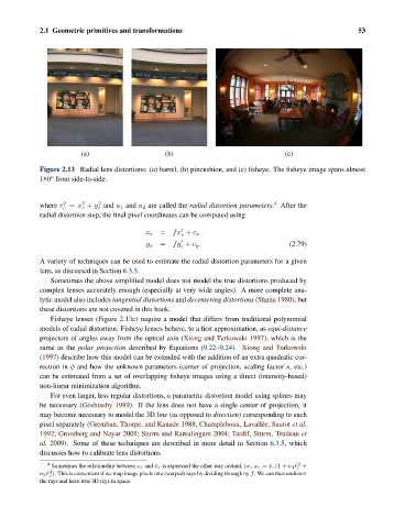
Figure 2.13 Radial lens distortions: (a) barrel, (b) pincushion, and (c) fisheye. The fisheye image spans almost
◦
180 from side-to-side.
2
2
4
2
where r = x + y and κ 1 and κ 2 are called the radial distortion parameters. After the
c c c
radial distortion step, the final pixel coordinates can be computed using
x s = fx + c x
c
y s = fy + c y . (2.79)
c
A variety of techniques can be used to estimate the radial distortion parameters for a given
lens, as discussed in Section 6.3.5.
Sometimes the above simplified model does not model the true distortions produced by
complex lenses accurately enough (especially at very wide angles). A more complete ana-
lytic model also includes tangential distortions and decentering distortions (Slama 1980), but
these distortions are not covered in this book.
Fisheye lenses (Figure 2.13c) require a model that differs from traditional polynomial
models of radial distortion. Fisheye lenses behave, to a first approximation, as equi-distance
projectors of angles away from the optical axis (Xiong and Turkowski 1997), which is the
same as the polar projection described by Equations (9.22–9.24). Xiong and Turkowski
(1997) describe how this model can be extended with the addition of an extra quadratic cor-
rection in φ and how the unknown parameters (center of projection, scaling factor s, etc.)
can be estimated from a set of overlapping fisheye images using a direct (intensity-based)
non-linear minimization algorithm.
For even larger, less regular distortions, a parametric distortion model using splines may
be necessary (Goshtasby 1989). If the lens does not have a single center of projection, it
may become necessary to model the 3D line (as opposed to direction) corresponding to each
pixel separately (Gremban, Thorpe, and Kanade 1988; Champleboux, Lavall´ ee, Sautot et al.
1992; Grossberg and Nayar 2001; Sturm and Ramalingam 2004; Tardif, Sturm, Trudeau et
al. 2009). Some of these techniques are described in more detail in Section 6.3.5, which
discusses how to calibrate lens distortions.
2
4 Sometimes the relationship between x c and ˆx c is expressed the other way around, i.e., x c =ˆx c(1 + κ 1 ˆr c +
4
κ 2 ˆr c ). This is convenient if we map image pixels into (warped) rays by dividing through by f. We can then undistort
the rays and have true 3D rays in space.