
Page 69 -
P. 69
48 2 Image formation
W/2
ș/2 f Z
(x,y,1)
(X,Y,Z)
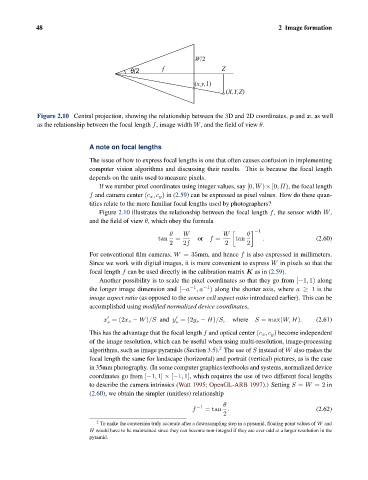
Figure 2.10 Central projection, showing the relationship between the 3D and 2D coordinates, p and x, as well
as the relationship between the focal length f, image width W, and the field of view θ.
A note on focal lengths
The issue of how to express focal lengths is one that often causes confusion in implementing
computer vision algorithms and discussing their results. This is because the focal length
depends on the units used to measure pixels.
If we number pixel coordinates using integer values, say [0,W)×[0,H), the focal length
f and camera center (c x ,c y ) in (2.59) can be expressed as pixel values. How do these quan-
tities relate to the more familiar focal lengths used by photographers?
Figure 2.10 illustrates the relationship between the focal length f, the sensor width W,
and the field of view θ, which obey the formula
−1
θ W W θ
tan = or f = tan . (2.60)
2 2f 2 2
For conventional film cameras, W =35mm, and hence f is also expressed in millimeters.
Since we work with digital images, it is more convenient to express W in pixels so that the
focal length f can be used directly in the calibration matrix K as in (2.59).
Another possibility is to scale the pixel coordinates so that they go from [−1, 1) along
the longer image dimension and [−a −1 ,a −1 ) along the shorter axis, where a ≥ 1 is the
image aspect ratio (as opposed to the sensor cell aspect ratio introduced earlier). This can be
accomplished using modified normalized device coordinates,
x =(2x s − W)/S and y =(2y s − H)/S, where S = max(W, H). (2.61)
s
s
This has the advantage that the focal length f and optical center (c x ,c y ) become independent
of the image resolution, which can be useful when using multi-resolution, image-processing
2
algorithms, such as image pyramids (Section 3.5). The use of S instead of W also makes the
focal length the same for landscape (horizontal) and portrait (vertical) pictures, as is the case
in 35mm photography. (In some computer graphics textbooks and systems, normalized device
coordinates go from [−1, 1] × [−1, 1], which requires the use of two different focal lengths
to describe the camera intrinsics (Watt 1995; OpenGL-ARB 1997).) Setting S = W =2 in
(2.60), we obtain the simpler (unitless) relationship
θ
−1
f = tan . (2.62)
2
2
To make the conversion truly accurate after a downsampling step in a pyramid, floating point values of W and
H would have to be maintained since they can become non-integral if they are ever odd at a larger resolution in the
pyramid.