
Page 377 - Construction Waterproofing Handbook
P. 377
REMEDIAL WATERPROOFING 8.37
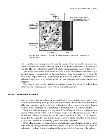
FIGURE 8.39 Schematic diagram of electro-osmosis equipment. (Courtesy of
Dytronic, Inc.)
rod) is installed into the adjacent soil from the exterior. If not accessible, an access hole
can be cored into the concrete structure floor or wall, installing the cathode from the inte-
rior side. The core hole is then sealed with a high-strength grout as shown in Fig. 8.40.
Anodes (ceramic-coated titanium) are installed in holes drilled in the concrete in a pat-
tern and amount recommended by the manufacturer. Once the anodes are in-place, the
holes should be patched using a high-strength grout as shown in Fig. 8.41. Both the anodes
and cathodes are wired in accordance with local electrical codes and connected to the con-
trol panel.
The control panel usually includes a warning system that alerts of malfunctions.
Otherwise, the system operates itself with no oversight necessary.
DIVERTOR SYSTEM REPAIRS
Divertor systems that fail to function are as difficult to access as exterior or positive sides
of below-grade building envelope areas. In many situations, it is more cost-effective to add
additional protection to reduce the water infiltrating to a level manageable by the divertor
systems. If the system has failed completely, a barrier system is the only alternative.
The first step in the process is to determine if the infiltration is due to negligent main-
tenance of the divertor system, such as clogged weeps or insufficient drainage away from
the structure (this can be determined by the process described in Chap. 13). If it is deter-
mined that the water flow entering the envelope is beyond the capability of the divertor
system, then remedial waterproofing systems should be considered.
Often when masonry envelope areas are involved, the water infiltration is due to excess
water entering through deteriorated mortar joints. The joints can be repaired using the
tuckpointing methods described earlier and the area retested to determine if the leakage is