
Page 406 - Construction Waterproofing Handbook
P. 406
10.8 CHAPTER TEN
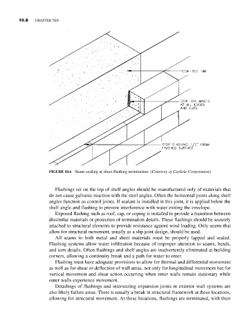
FIGURE 10.6 Seam sealing at sheet flashing termination. (Courtesy of Carlisle Corporation)
Flashings set on the top of shelf angles should be manufactured only of materials that
do not cause galvanic reaction with the steel angles. Often the horizontal joints along shelf
angles function as control joints. If sealant is installed in this joint, it is applied below the
shelf angle and flashing to prevent interference with water exiting the envelope.
Exposed flashing such as roof, cap, or coping is installed to provide a transition between
dissimilar materials or protection of termination details. These flashings should be securely
attached to structural elements to provide resistance against wind loading. Only seams that
allow for structural movement, usually as a slip joint design, should be used.
All seams in both metal and sheet materials must be properly lapped and sealed.
Flashing systems allow water infiltration because of improper attention to seams, bends,
and turn details. Often flashings and shelf angles are inadvertently eliminated at building
corners, allowing a continuity break and a path for water to enter.
Flashing must have adequate provisions to allow for thermal and differential movement
as well as for shear or deflection of wall areas, not only for longitudinal movement but for
vertical movement and shear action occurring when inner walls remain stationary while
outer walls experience movement.
Detailings of flashings and intersecting expansion joints in exterior wall systems are
also likely failure areas. There is usually a break in structural framework at these locations,
allowing for structural movement. At these locations, flashings are terminated, with their