
Page 227 - Corrosion Engineering Principles and Practice
P. 227
202 C h a p t e r 6 R e c o g n i z i n g t h e F o r m s o f C o r r o s i o n 203
240
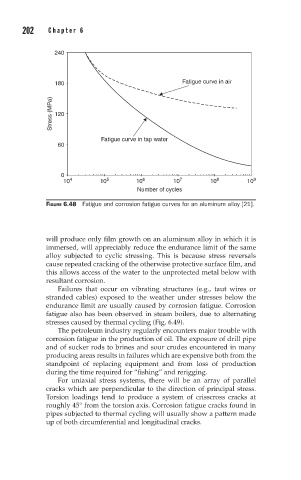
180 Fatigue curve in air
Stress (MPa) 120
Fatigue curve in tap water
60
0
10 4 10 5 10 6 10 7 10 8 10 9
Number of cycles
FIGURE 6.48 Fatigue and corrosion fatigue curves for an aluminum alloy [21].
will produce only film growth on an aluminum alloy in which it is
immersed, will appreciably reduce the endurance limit of the same
alloy subjected to cyclic stressing. This is because stress reversals
cause repeated cracking of the otherwise protective surface film, and
this allows access of the water to the unprotected metal below with
resultant corrosion.
Failures that occur on vibrating structures (e.g., taut wires or
stranded cables) exposed to the weather under stresses below the
endurance limit are usually caused by corrosion fatigue. Corrosion
fatigue also has been observed in steam boilers, due to alternating
stresses caused by thermal cycling (Fig. 6.49).
The petroleum industry regularly encounters major trouble with
corrosion fatigue in the production of oil. The exposure of drill pipe
and of sucker rods to brines and sour crudes encountered in many
producing areas results in failures which are expensive both from the
standpoint of replacing equipment and from loss of production
during the time required for “fishing” and rerigging.
For uniaxial stress systems, there will be an array of parallel
cracks which are perpendicular to the direction of principal stress.
Torsion loadings tend to produce a system of crisscross cracks at
roughly 45° from the torsion axis. Corrosion fatigue cracks found in
pipes subjected to thermal cycling will usually show a pattern made
up of both circumferential and longitudinal cracks.