
Page 204 - DSP Integrated Circuits
P. 204
5.2 Parasitic Oscillations 189
truncation of the signal values. Parasitic oscillations can, of course, also be caused
by interaction between different types of nonlinearities. In this section, we will
illustrate some of the most common phenomena. We stress that nonlinear effects
are complex and by no means fully understood. For example, it has recently been
shown that digital filters with sufficiently large word length exhibit near-chaotic
behavior [3,19].
5.2.1 Zero-Input Oscillations
One of the most studied cases, due to its simplicity, is when the input signal, x(n), to
a recursive filter suddenly becomes zero. The output signal of a stable linear filter
will tend to zero, but the nonlinear filter may enter a so-called zero-input limit cycle.
Zero-input parasitic oscillations can be very disturbing, for example, in a
speech application. At the beginning of a silent part in the speech, the input signal
becomes zero. The output signal should ideally decay to zero, but a parasitic oscil-
lation may instead occur in the nonlinear filter. The magnitude and frequency
spectra of the particular oscillation depend on the values that the delay elements
have at the moment the input becomes zero. Most oscillations will, however, have
large frequency components in the passband of the filter and they are more harm-
ful, from a perception point of view, than wide-band quantization noise, since the
human ear is sensitive to periodic signals. Comparison of parasitic oscillations and
quantization noise should therefore be treated with caution.
Zero-input limit cycles can be eliminated by using a longer data word length
inside the filter and discarding the least significant bits at the output. The number
of extra bits required can be determined from estimates of the maximum magni-
tude of the oscillations [22].
EXAMPLE 5.1
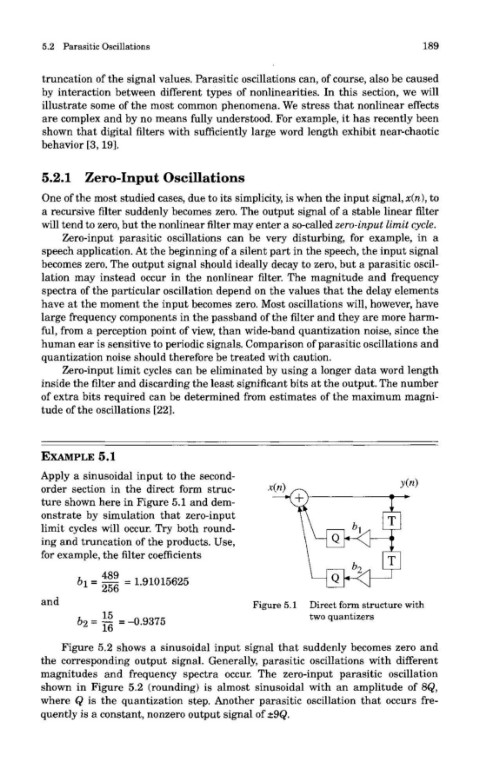
Apply a sinusoidal input to the second-
order section in the direct form struc-
ture shown here in Figure 5.1 and dem-
onstrate by simulation that zero-input
limit cycles will occur. Try both round-
ing and truncation of the products. Use,
for example, the filter coefficients
and Figure 5.1 Direct form structure with
two quantizers
Figure 5.2 shows a sinusoidal input signal that suddenly becomes zero and
the corresponding output signal. Generally, parasitic oscillations with different
magnitudes and frequency spectra occur. The zero-input parasitic oscillation
shown in Figure 5.2 (rounding) is almost sinusoidal with an amplitude of 8Q,
where Q is the quantization step. Another parasitic oscillation that occurs fre-
quently is a constant, nonzero output signal of ±9Q.