
Page 206 - DSP Integrated Circuits
P. 206
5.2 Parasitic Oscillations 191
analyze or suppress, is the constant-input parasitic oscillation which, of course,
may occur when the input signal is constant [4]. Unfortunately, the work based on
special input signals can not easily be extended to more general classes of signals.
Except for some second-order sections, based on either state-space structures [14,
25] or wave digital niters that are free of all types of parasitic oscillations, it seems
that these approaches are generally unsuccessful.
5.2.2 Overflow Oscillations
Large errors will occur if the sig-
nal overflows the finite number
range. Overflow will not only
cause large distortion, but may
also be the cause of parasitic
oscillations in recursive algo-
rithms. A two's-complement rep-
resentation of negative numbers
is usually used in digital hard-
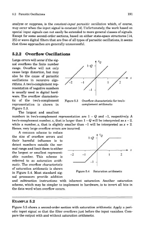
ware. The overflow characteris-
tic of the two's-complement Figure 5.3 Overflow characteristic for two's-
representation is shown in complement arithmetic
Figure 5.3.
The largest and smallest
numbers in two's-complement representation are 1 - Q and -1, respectively. A
two's-complement number, x, that is larger than 1 - Q will be interpreted as x - 2,
while a number, x, that is slightly smaller than —1 will be interpreted as x + 2.
Hence, very large overflow errors are incurred.
A common scheme to reduce
the size of overflow errors and
their harmful influence is to
detect numbers outside the nor-
mal range and limit them to either
the largest or smallest represent-
able number. This scheme is
referred to as saturation arith-
metic. The overflow characteristic
of saturation arithmetic is shown
in Figure 5.4. Most standard sig- Figure 5.4 Saturation arithmetic
nal processors provide addition
and subtraction instructions with inherent saturation. Another saturation
scheme, which may be simpler to implement in hardware, is to invert all bits in
the data word when overflow occurs.
EXAMPLE 5.2
Figure 5.5 shows a second-order section with saturation arithmetic. Apply a peri-
odic input signal so that the filter overflows just before the input vanishes. Com-
pare the output with and without saturation arithmetic.