
Page 211 - DSP Integrated Circuits
P. 211
196 Chapter 5 Finite Word Length Effects
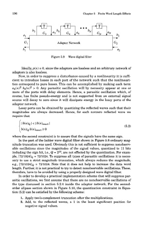
Figure 5.9 Wave digital filter
Ideally, p(n) = 0, since the adaptors are lossless and an arbitrary network of
adaptors is also lossless.
Now, in order to suppress a disturbance caused by a nonlinearity it is suffi-
cient to introduce losses in each port of the network such that the nonlineari-
ties correspond to pure losses. This can be accomplished by making each term
2
2
a&Oi) &&(ft) > 0. Any parasitic oscillation will by necessity appear at one or
more of the ports with delay elements. Hence, a parasitic oscillation which, of
course, has finite pseudo-energy and is not supported from an external signal
source will decay to zero since it will dissipate energy in the lossy ports of the
adaptor network.
Lossy ports can be obtained by quantizing the reflected waves such that their
magnitudes are always decreased. Hence, for each nonzero reflected wave we
require that
where the second constraint is to assure that the signals have the same sign.
In the part of the ladder wave digital filter shown in Figure 5.8 ordinary mag-
nitude truncation was used. Obviously this is not sufficient to suppress nonobserv-
able oscillations since the magnitudes of the signal values, quantized to 11 bits
10
including the sign bit, i.e., Q = 2 , are not effected by the quantization. For exam-
ple, [72/1024] Q = 72/1024. To suppress all types of parasitic oscillations it is neces-
sary to use a strict magnitude truncation, which always reduces the magnitude,
e.g., [72/1024]Q = 72/1024. Note that it does not help to increase the data word
length. Further, it is not practical to try to detect nonobservable oscillations. These,
therefore, have to be avoided by using a properly designed wave digital filter.
In order to develop a practical implementation scheme that will suppress par-
asitic oscillations, we first assume that there are no nonobservable oscillations of
the type discussed in section 5.2.4 inside the adaptor network. For the second-
order allpass section shown in Figure 5.10, the quantization constraint in Equa-
tion (5.2) can be satisfied by the following scheme:
1. Apply two's-complement truncation after the multiplications.
2. Add, to the reflected waves, a 1 in the least significant position for
negative signal values.