
Page 214 - DSP Integrated Circuits
P. 214
5.5 Scaling of Signal Levels 199
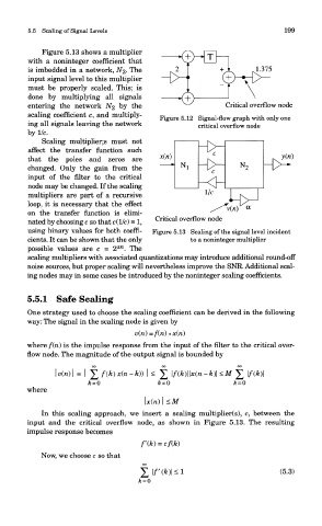
Figure 5.13 shows a multiplier
with a noninteger coefficient that
is imbedded in a network, NZ- The
input signal level to this multiplier
must be properly scaled. This; is
done by multiplying all signals
entering the network NZ by the
scaling coefficient c, and multiply-
Figure 5.12 Signal-flow graph with only one
ing all signals leaving the network critical overflow node
by 1/c.
Scaling multipliers must not
affect the transfer function such
that the poles and zeros are
changed. Only the gain from the
input of the filter to the critical
node may be changed. If the scaling
multipliers are part of a recursive
loop, it is necessary that the effect
on the transfer function is elimi-
nated by choosing c so that c(l/c) = 1,
using binary values for both coeffi- Figure 5.13 Scaling of the signal level incident
cients. It can be shown that the only to a noninteger multiplier
±n
possible values are c = 2 . The
scaling multipliers with associated quantizations may introduce additional round-off
noise sources, but proper scaling will nevertheless improve the SNR. Additional scal-
ing nodes may in some cases be introduced by the noninteger scaling coefficients.
5.5.1 Safe Scaling
One strategy used to choose the scaling coefficient can be derived in the following
way: The signal in the scaling node is given by
where f(ri) is the impulse response from the input of the filter to the critical over-
flow node. The magnitude of the output signal is bounded by
where
In this scaling approach, we insert a scaling multiplier(s), c, between the
input and the critical overflow node, as shown in Figure 5.13. The resulting
impulse response becomes
Now, we choose c so that