
Page 212 - DSP Integrated Circuits
P. 212
5.4 Quantization In WDFs 197
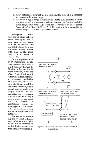
3. Apply saturation, or invert all bits including the sign bit, if a reflected
wave exceeds the signal range.
4. The internal signal range is increased by 1 bit to [2, 2], since the input to
a multiplier with a noninteger coefficient may not overflow the available
signal range. This word length extension is indicated by a box labeled
"sign extend" in Figures 5.10 and 5.11. The word length is reduced to its
normal range [1,1[ at the output of the section.
Bireciprocal lattice
wave digital filters will sup-
press zero-input oscilla-
tions even if the second
constraint is removed. The
simplified scheme for a sec-
ond-order allpass section
with poles on the imagi-
nary axis is shown in
Figure b. 11.
In an implementation
of an incremental pseudo-
passive wave digital filter it
is not necessary to start the
filtering by first zeroing the
delay elements, since any
effect of initial values will
fade away and can not cause
a permanent oscillation.
This possibility often leads
to a significant simplifica-
tion of the hardware, since a
special start-up mode is no
longer required. It also
saves time and reduces code
size in a software imple-
mentation. It is also possi-
ble to develop a
quantization scheme for
floating-point arithmetic,
although this leads to long
and more complicated com-
putations.
The equations describ-
ing the two-port adaptors
used in lattice wave digital
filters can be modified to
exploit the features of stan- Figure 5.10 Quantization in a second-order WDF of
dard signal processors [11]. allpass type