
Page 333 - DSP Integrated Circuits
P. 333
318 Chapter 7 DSP System Design
A cyclo-static schedule is characterized by a pattern in the processor-time
space for one iteration and its principal lattice vector. The pattern is repeated and
displaced in both the time and processor domains by the vector JL. The first compo-
nent of the principal lattice vector gives the spatial displacement. When the pro-
cessor component is zero, the schedule is called static schedule. The second
component vector denotes the time shift from one iteration to the other. Without
blocking of the operations belonging to several sample intervals, this component is
equal to the iteration period.
EXAMPLE 7.6
Consider the second-order section in direct form II shown in Figure 7.10. Assume
that two types of processors are available: multipliers with delay 2 and adders
with delay 1.
The iteration period bound is
The processor bounds for adders and multipliers are |~1 • 4/4~| = 1 and [2 • 5/4l = 3,
respectively.
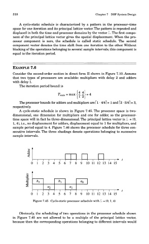
A cyclo-static schedule is shown in Figure 7.45. The processor space is two-
dimensional, one dimension for multipliers and one for adder, so the processor-
time space will in fact be three-dimensional. The principal lattice vector is JL = (0,
1, 4), i.e., no displacement for adders, displacement equal to 1 for multipliers, and
sample period equal to 4. Figure 7.46 shows the processor schedule for three con-
secutive intervals. The three shadings denote operations belonging to successive
sample intervals.
Figure 7.45 Cyclo-static processor schedule with JL = (0,1, 4)
Obviously, the scheduling of two operations in the processor schedule shown
in Figure 7.45 are not allowed to be a multiple of the principal lattice vector,
because then the corresponding operations belonging to different intervals would