
Page 392 - DSP Integrated Circuits
P. 392
8.8 Wave Front Arrays 377
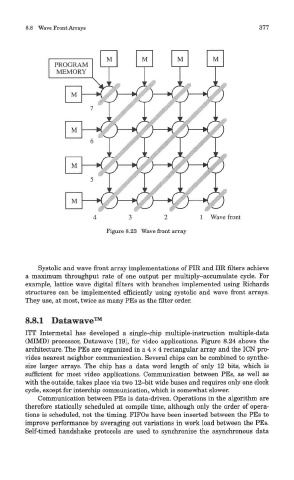
Figure 8.23 Wave front array
Systolic and wave front array implementations of FIR and IIR niters achieve
a maximum throughput rate of one output per multiply-accumulate cycle. For
example, lattice wave digital niters with branches implemented using Richards
structures can be implemented efficiently using systolic and wave front arrays.
They use, at most, twice as many PEs as the filter order.
8.8.1 Datawave™
ITT Intermetal has developed a single-chip multiple-instruction multiple-data
(MIMD) processor, Datawave [19], for video applications. Figure 8.24 shows the
architecture. The PEs are organized in a 4 x 4 rectangular array and the ICN pro-
vides nearest neighbor communication. Several chips can be combined to synthe-
size larger arrays. The chip has a data word length of only 12 bits, which is
sufficient for most video applications. Communication between PEs, as well as
with the outside, takes place via two 12-bit wide buses and requires only one clock
cycle, except for interchip communication, which is somewhat slower.
Communication between PEs is data-driven. Operations in the algorithm are
therefore statically scheduled at compile time, although only the order of opera-
tions is scheduled, not the timing. FIFOs have been inserted between the PEs to
improve performance by averaging out variations in work load between the PEs.
Self-timed handshake protocols are used to synchronize the asynchronous data