
Page 387 - DSP Integrated Circuits
P. 387
372 Chapter 8 DSP Architectures
8.6.1 Interconnection Topologies
To exploit parallelism efficiently, a parallel or distributed system must be designed
to minimize communication overhead between processors. A given communication
strategy might support one application well but be inefficient for others. A com-
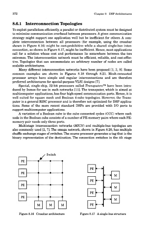
plete interconnection between all processors (for example, using the crossbar
shown in Figure 8.16) might be cost-prohibitive while a shared single-bus inter-
connection, as shown in Figure 8.17, might be inefficient. Hence, most applications
call for a solution whose cost and performance lie somewhere between the two
extremes. The interconnection network must be efficient, reliable, and cost-effec-
tive. Topologies that can accommodate an arbitrary number of nodes are called
scalable architectures.
Many different interconnection networks have been proposed [1, 3, 9]. Some
common examples are shown in Figures 8.18 through 8.21. Mesh-connected
processor arrays have simple and regular interconnections and are therefore
preferred architectures for special-purpose VLSI designs [7].
Special, single-chip, 32-bit processors called Transputers™ have been intro-
duced by Inmos for use in such networks [11]. The transputer, which is aimed at
multicomputer applications, has four high-speed communication ports. Hence, it is
well suited for square mesh and Boolean 4-cube topologies. However, the Trans-
puter is a general RISC processor and is therefore not optimized for DSP applica-
tions. Some of the more recent standard DSPs are provided with I/O ports to
support multicomputer applications.
A variation of a Boolean cube is the cube connected cycles (CCC) where each
node in the Boolean cube consists of a number of PE-memory pairs where each PE-
memory pair needs only three ports.
Multistage interconnection networks (MICN) and multiple-bus topologies are
also commonly used [2, 7]. The omega network, shown in Figure 8.20, has multiple
shuffle exchange stages of switches. The source processor generates a tag that is the
binary representation of the destination. The connection switches in the ith stage
Figure 8.16 Crossbar architecture Figure 8.17 A single-bus structure