
Page 384 - DSP Integrated Circuits
P. 384
8.4 Ideal DSP Architectures 369
which in turn releases the self-timed module. When the module has finished its
task, it issues the Done signal. The Done signal can then act as an Enable signal so
that the host can initiate the next transaction [8].
A problem with asynchronous and self-timed systems is that the time differ-
ence between the Enable and Done signals may be so small, or even negative, that
the handshaking malfunctions. Also noise in the signals may cause errors or put
the latches into a metastable state where neither of the outputs are within their
low or high voltage ranges. In theory, the latch may stay in this undefined state
indefinitely.
8.4.7 Autonomous Bit-Serial PEs
A problem associated with bit-serial PEs is their high clock frequency—e.g., 200 to
700 MHz. It is not possible to feed these clocks into a chip through the external
pins, so they must be generated internally.
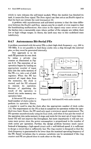
One approach is to let
each PE generate its own clock
by using a private ring
counter as illustrated in Fig-
ure 8.12. The execution of an
operation begins by loading an
appropriate number of input
data into the cache memory of
the PE—i.e., into a set of shift
registers. When the PE has
received all input data from
the memories, the clock is
started, and the PE released
to execute its operation.
Because of pipelining the
result of the operation is
stored into cache memory one
operation later.
A bit-serial PE requires a
fixed number of clock cycles to Figure 8.12 Self-timed PE with cache memory
perform its operation. Hence,
a counter is used to stop the clock after the appropriate number of clock cycles
[15]. The requirement on the PE is that it completes its operation within the spec-
ified time limit. Hence, the PE need only meet a minimum speed requirement. The
PE operates asynchronously using its local clock, and when it has put the result of
the operation into cache memory it stops and waits for the next set of input data. A
faster PE will not improve the throughput, but more importantly it will not con-
sume more power, since the power consumption is proportional to the number of
clock cycles per operation. Further, the design problem becomes much easier.
Instead of designing a high-speed circuit with a well-defined speed, it is sufficient
to design a circuit that is sufficiently fast. The ring counter is designed so that the
clock frequency is guaranteed to be lower than the maximal operating frequency of
the PE. Speed variations due to process variations can be minimized if the ring
counter and PE are placed close to each other on the chip.